fast-robots
Lab 3
The goal of this lab is to familiarize us with the Sparkfun VL53L1X time-of-flight (ToF) sensors and to explore parametric impact on effective use with our car robots in terms of sampling speed and value in sensor readings.
Prelab
According to the VL53L1X datasheet, the I2C bus on the ToF sensors default to device address 0x52.
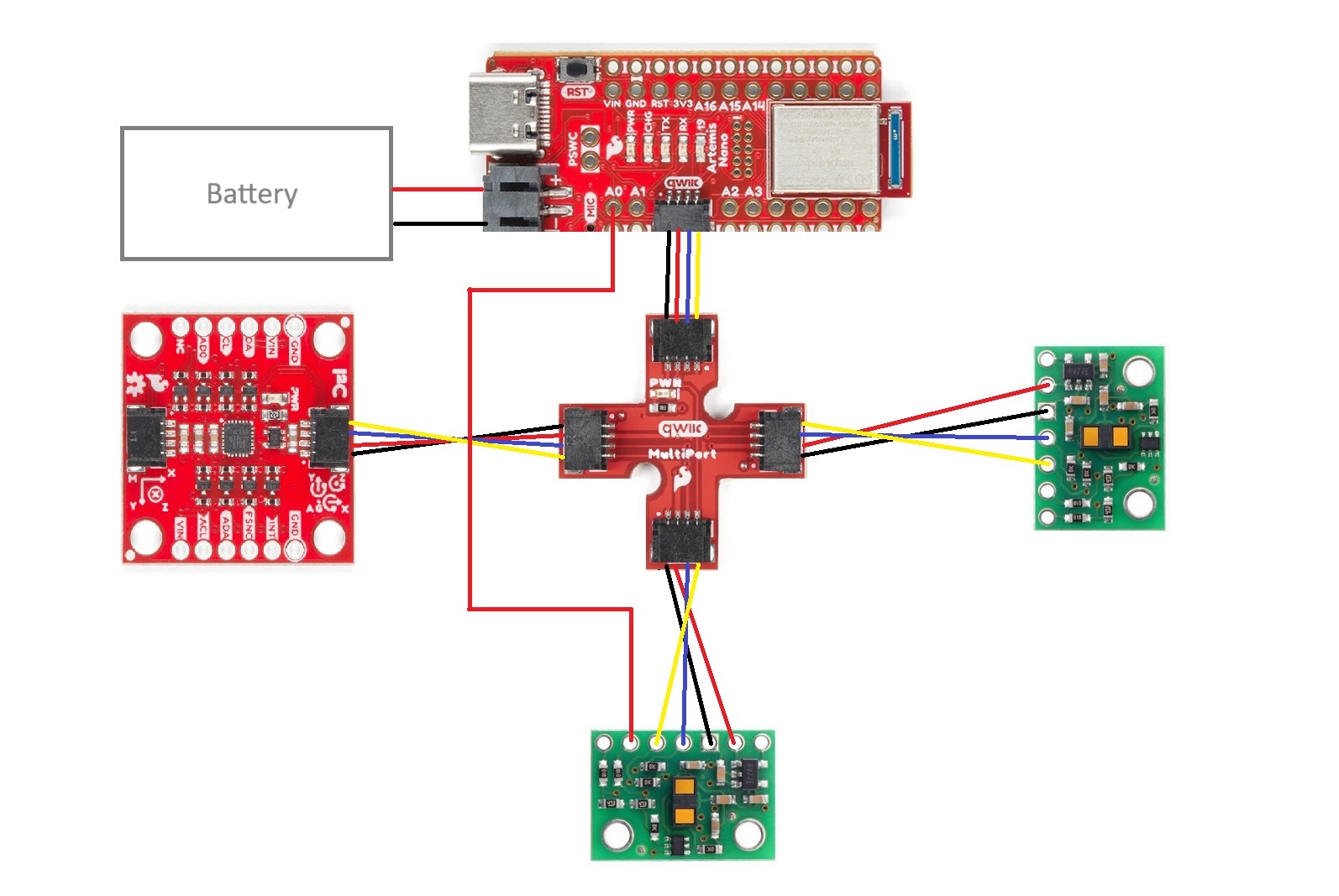
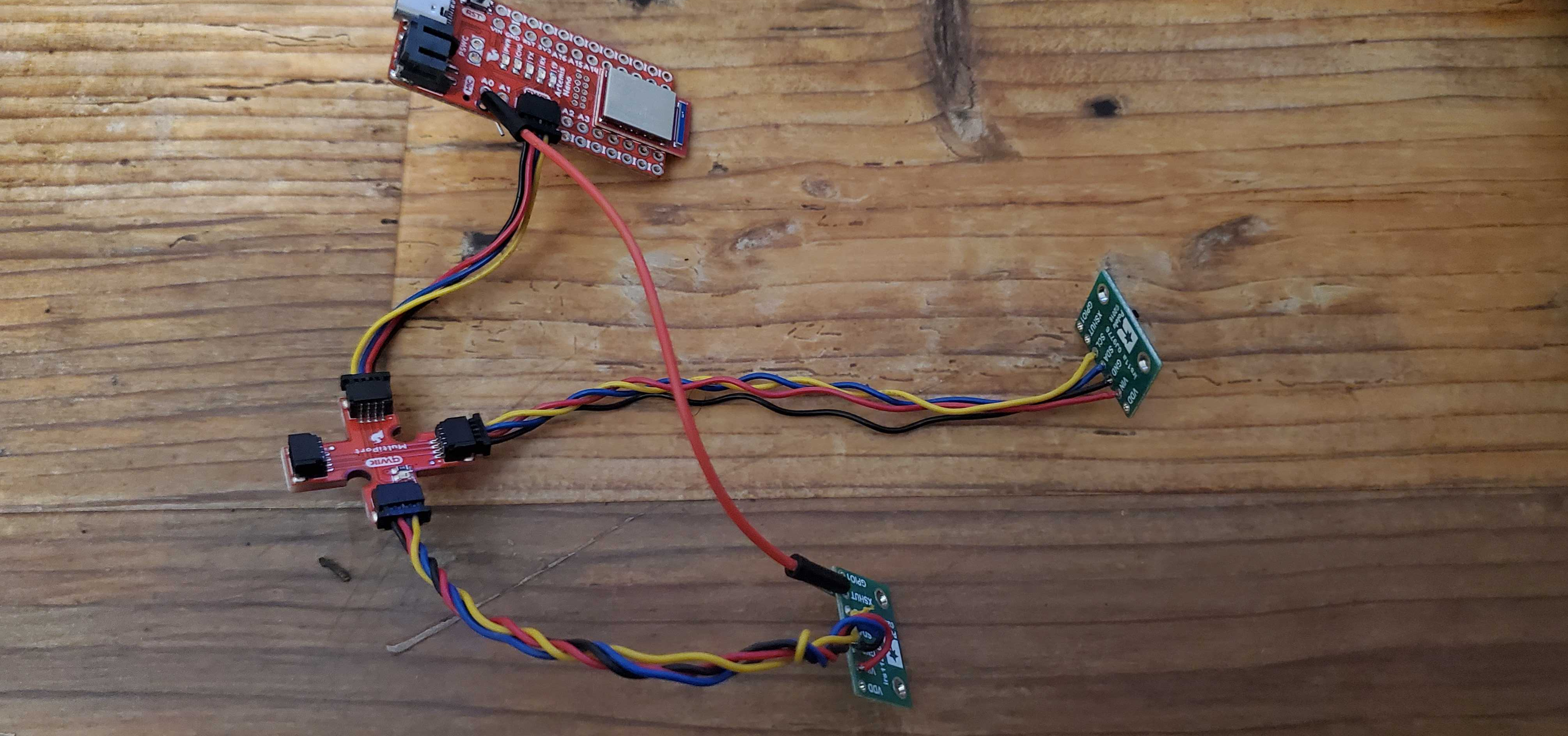
I will adhere to the wiring diagram shown below. Having one ToF sensor in the front of the robot is clearly valuable for observing obstacles directly in the robot’s path and adjusting accordingly. I wanted vision on one side of the robot so that it can observe obstacles or maze border walls to its side, which would otherwise require a 90 degree turn in either direction that could sacrifice movement efficiency. The decision of right side over left side was arbitrary, and obstacles on the left side will be missed without rotating to change the ToF sensors’ field of vision.
In the diagram below, red connections from the QWIIK board to the sensors correspond to VIN, black connections to GND, blue connections to SDA, and yellow connections to SCL. There is one stray red connection from the XSHUT port on the side sensor to the A0 port on the Artemis board for later use in supporting both ToF sensors.
Lab Tasks
One sensor
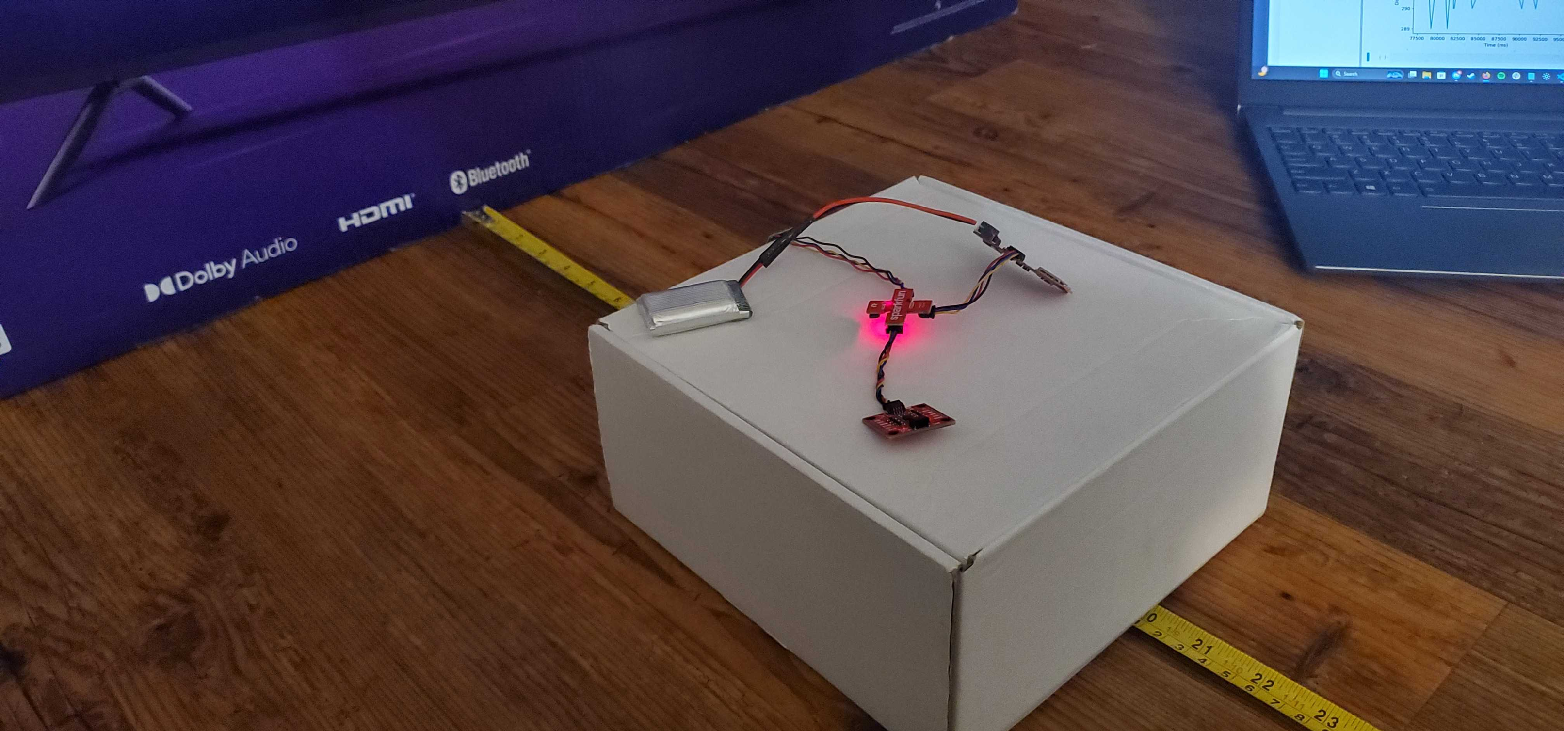
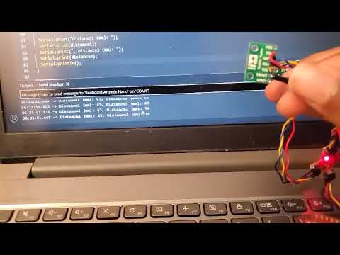
After clipping the ends of two QWIIC cables and soldering one to each ToF sensor, I tested them with the RedBoard Artemis Nano. I connected the first ToF sensor, QWIIC breakout board, and Artemis board as shown below:
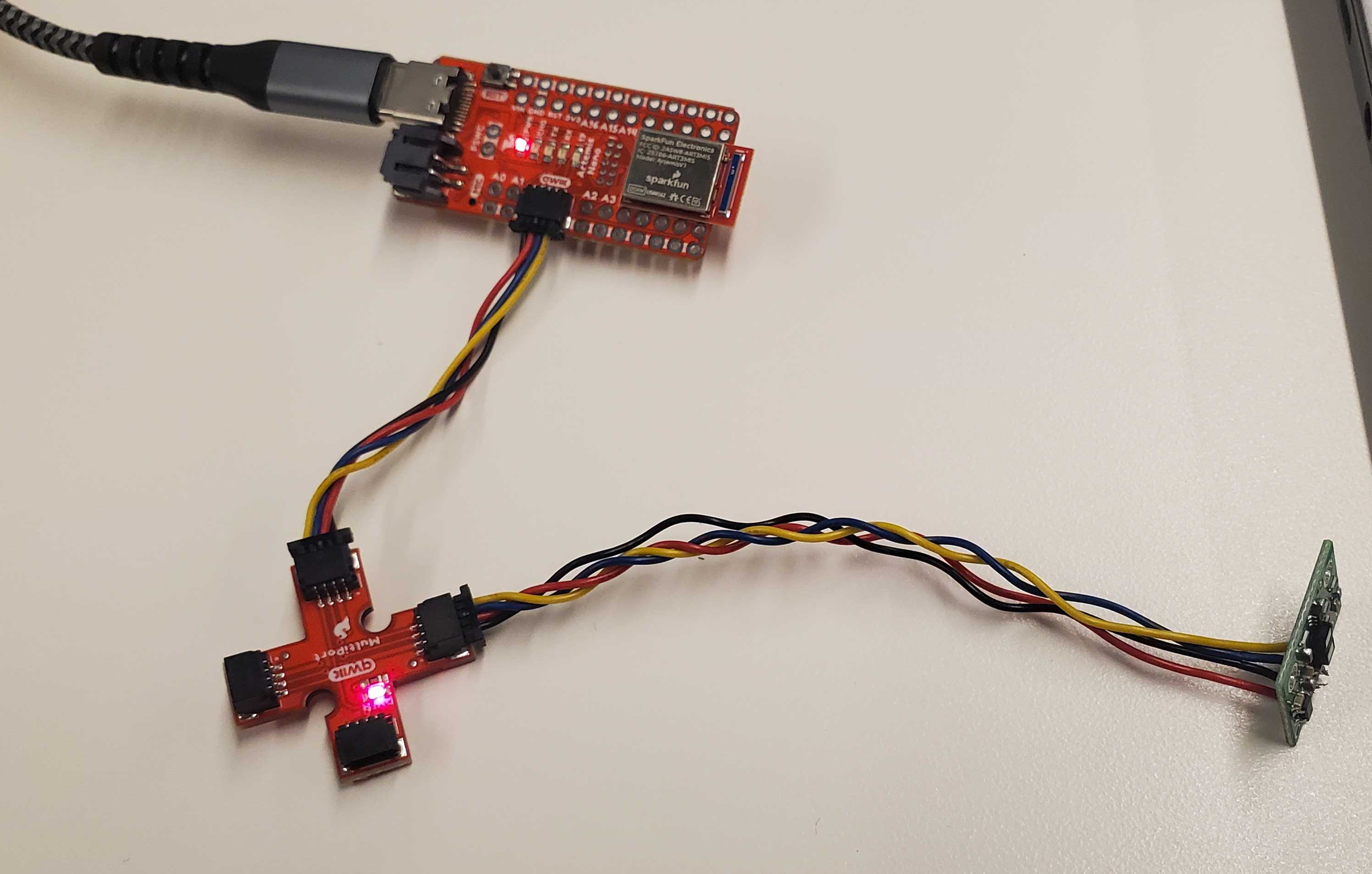
Running the Example05_wire_I2C file from the Apollo3 library, I scanned the breakout board to confirm connection to the ToF sensor. I initially expected an address of 0x52 as aforementioned, but read an address of 0x29 instead. This made sense in the context of the least significant bit signaling read/write. With the original address of 0x52 being 0b1010010, removing that last bit yields the true I2C address of 0b101001, or 0x29.

I chose to use the short-distance mode. The datasheet showed a consistent maximum distance of ~130cm for the short-distance mode, which seems sufficient for tasks such as navigating a maze. While the long-distance mode did reach up to 360cm in ideal conditions, its significant sensitivity to ambient light and target reflectance suggest little tolerance for more realistic conditions, so the short-distance mode seems more appropriate.
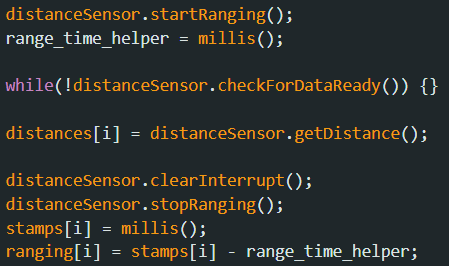
Leaving the sensor in short-distance mode, I used the Example1_ReadDistance file from the ToF sensor Arduino library. In a well-lit room, I used a small cardboard box to point the sensor flat at a larger cardboard box and take 25 distance samples at distances from 10cm to 200cm in increments of 10cm. I used the code from Example1_ReadDistance to modify ble_arduino.ino to record ToF sensor data.
There may be some error due to the slight slope on the boxes and the size of the sensor itself, but the average sensor data seem very consistent with the true measurements.
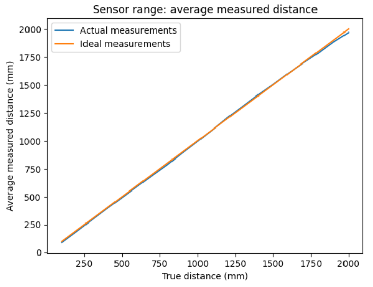
For accuracy, the measurement error was primarily slight underestimates by ~10mm, which is likely due to the aforementioned. There is a sharp drop-off as the distance approaches 200cm, showing that we are reaching the end of the sensor’s true range.

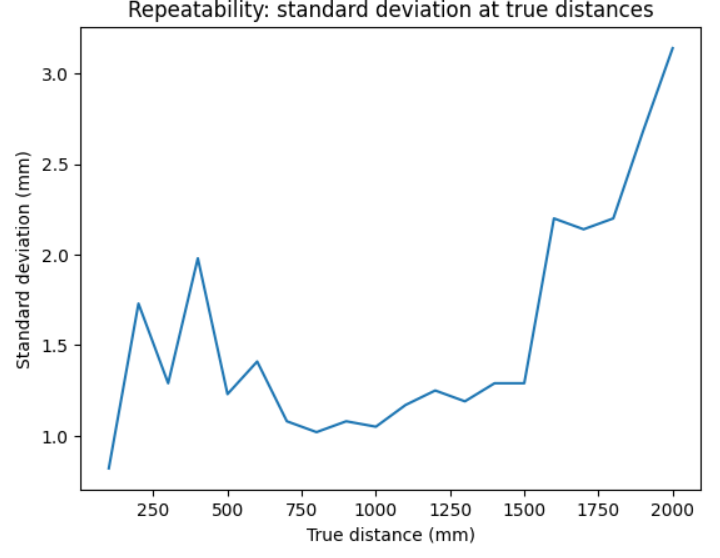
For repeatability, we consider the standard deviation from the sample at each distance. The standard deviation stays relatively steady until it spikes at around 160cm, showing uncertainty in measured data beyond the apparent sensor range.
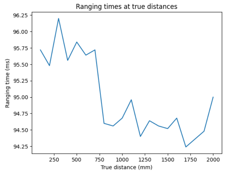
Finally, ranging time held consistently around 95 ms. This is likely due to the inefficient while-loop wait for sensor data, which is better optimized later.
 \
\
Two sensors
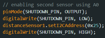
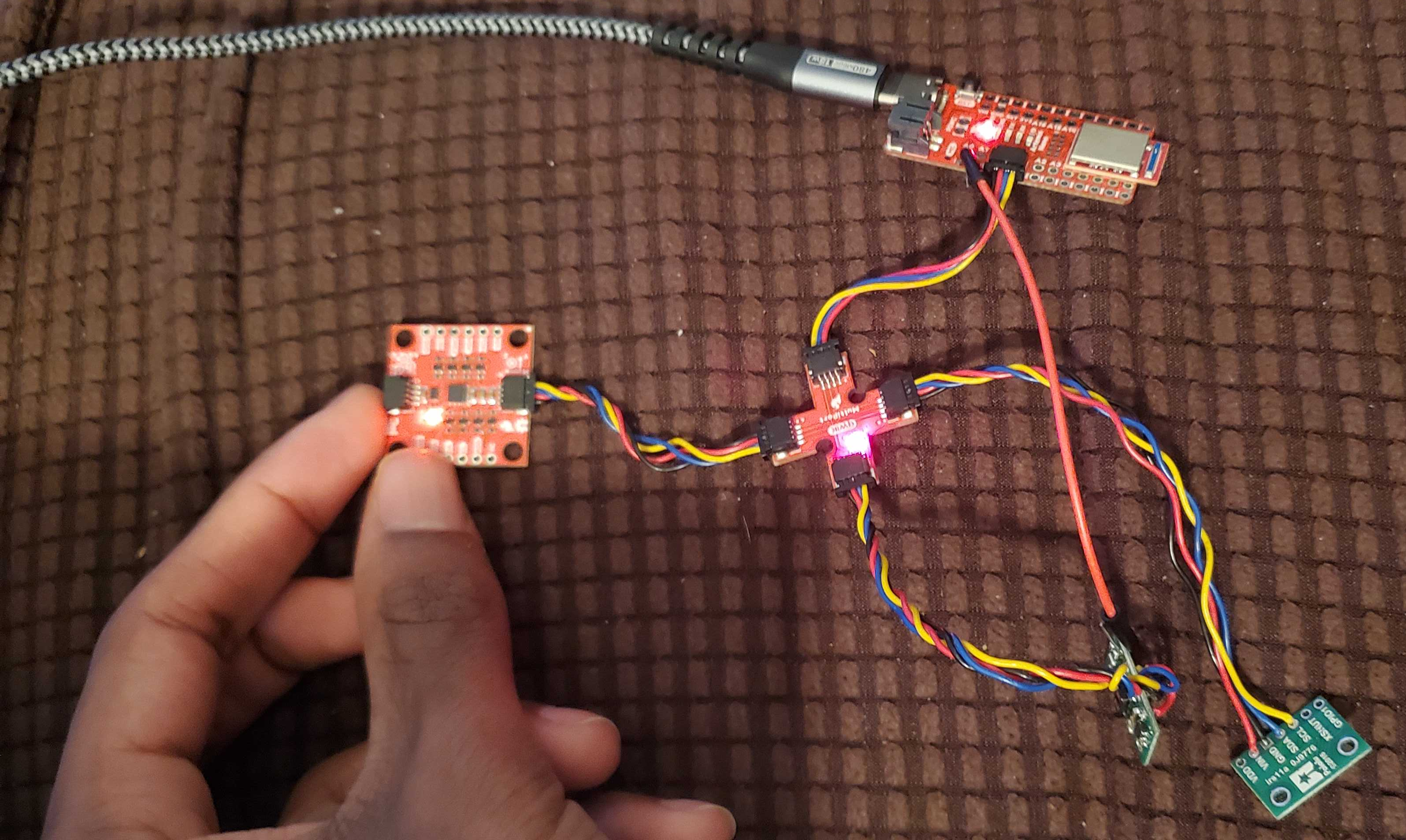
I now have both ToF sensors connected to the breakout board. Both sensors default to the same address, so I had to change the address of one of the boards. I connected a wire from the XSHUT port on one board to a pin on the Artemis (arbitrarily picking A0). Now, I can set XSHUT low during setup, change the address of the first ToF sensor, and then set it high again to wake it back up with the new address.
I made some adjustments to the Example1_ReadDistance code to display both sensor outputs. In the video, I show both sensors actively making independent readings by rotating them individually towards the ceiling.
Measurement optimization
Following the lab handout recommendation, I added a new command to ble_arduino.ino. This function repeatedly prints the current program time elapsed, queries whether new ToF sensor data is available from both sensors, and prints said data if it is available.
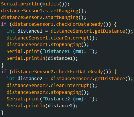
A test run of 250 iterations showed an average loop execution rate of around 3.24 ms per iteration. Of these, the first sensor had 3 measurements, and the other sensor had 4 measurements. The current limiting factor is clearly the speed that the ToF sensors themselves acquire data.
Three sensors
Finally, I connect the IMU to the third slot on the breakout board. The IMU’s I2C address is 0x69, which is different from the other two addresses, so no other changes need to be made.
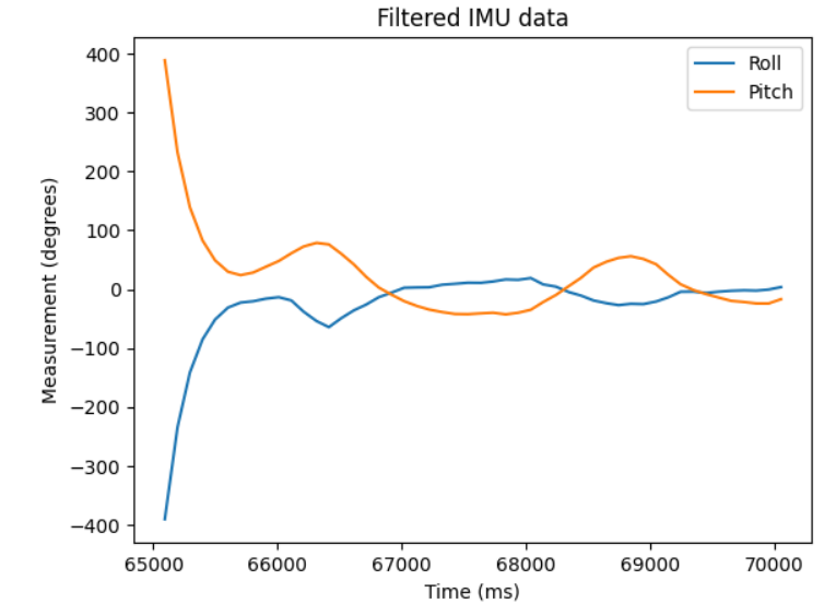
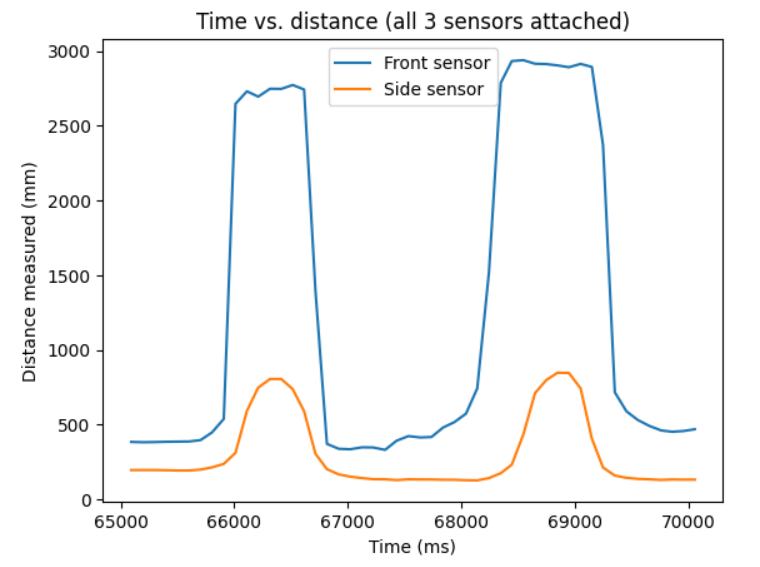
Like before, I demonstrate all three sensors making measurements. I added another command which records the distance readings from the ToF sensors and the angle data from the IMU using code from Lab 2. This data is stored in separate arrays which are sent to my computer via Bluetooth.
For the following plots, I recorded 50 datapoints during which the IMU and both ToF sensors had all recorded data. I adjusted my environment and angled my hand up and down trying to get the distance measurements from both ToF sensors and the measured pitch and roll from the IMU to all oscillate at once. Note that a typo from carrying code from previous labs leads to the unrealistic spike at the start of the IMU data.